
Build a Flat, Solid Floor From the Joists Up
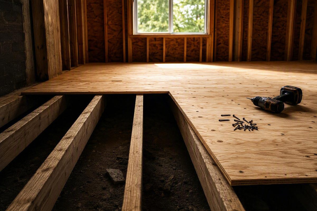
Learning how to install a subfloor is less about copying one panel thickness or fastening pattern than about confirming a complete floor assembly. The framing, panel rating, edge support, adhesive, fasteners, and finished flooring must work together.
This planning and installation guide covers structural plywood or oriented strand board (OSB) installed directly over exposed floor joists. It does not replace engineered drawings, locally applicable requirements, or current instructions from the selected panel, joist, adhesive, fastener, and flooring manufacturers.
Before buying materials, answer four questions:
- What framing system is below the panels?
- What structural panel is approved for that framing?
- How must the panel be supported, adhered, and mechanically fastened?
- What will the finished flooring require from the completed subfloor?
Once those answers are documented, the physical work follows a disciplined sequence: inspect, support, lay out, dry-fit, glue, place, space, fasten, and inspect.
By Dev Okonjo, drawing on two decades of flooring installation and repair work.
Confirm What Kind of Subfloor Project You Have
A structural subfloor is the panel layer installed over floor joists to support the finished flooring and transfer loads into the framing. This guide focuses on installing or replacing structural plywood or OSB while the joists are exposed.
That is different from adding plywood underlayment or a second panel layer over an intact subfloor. Second-layer seam placement, adhesive practices, and fastening logic may differ; in some assemblies, fasteners intentionally avoid the joists. Do not apply second-layer underlayment advice to panels spanning exposed framing—or structural-subfloor instructions to an underlayment layer.
Localized replacement also requires more than cutting a neat rectangle. Every new load-bearing edge must receive the support required by the assembly, even if the original sheet extended beyond the repair opening.
Make a project specification worksheet
Record these items before demolition or material ordering:
| Item | What to verify | Where to find it |
|---|---|---|
| Joists | Conventional lumber, I-joists, floor trusses, or another system | Existing product markings, plans, joist documentation |
| Joist layout | Spacing, span, direction, bearing points, and condition | Site measurement and engineered drawings |
| Panel material | Plywood or OSB | Plans and panel selection |
| Panel identification | Grade, thickness, span rating, and exposure rating | Panel stamp and product literature |
| Panel direction | Strength axis or plywood face-grain orientation | Panel stamp and manufacturer instructions |
| Edge system | Square edge, tongue-and-groove, self-spacing, or proprietary joint | Panel edge and product instructions |
| Edge support | Ends, perimeters, openings, patches, and transitions requiring blocking | Plans, panel instructions, and framing-system details |
| Adhesive | Compatibility with the panel and framing | Adhesive label and technical data |
| Fasteners | Category, type, size, corrosion resistance, and required penetration | Plans and panel, joist, and fastener documentation |
| Fastening schedule | Edge, perimeter, and intermediate-support spacing | Approved plans or governing product instructions |
| Finished floor | Hardwood, laminate, vinyl, tile, stone, carpet, or another covering | Selected flooring specification |
| Final substrate criteria | Moisture, flatness, stiffness, reinforcement, and underlayment | Finished-floor instructions |
A worked installation demonstration used 3/4-inch tongue-and-groove plywood over joists spaced 16 inches on center, but those were conditions of that project—not a general specification (Home Repair Tutor installation demonstration). On your worksheet, record those fields as “unresolved” until the panel rating and governing documents confirm them.
Use this document-precedence workflow:
- Start with engineered drawings or approved project documents.
- Check locally applicable requirements.
- Identify the framing system and consult its documentation.
- match the panel stamp and instructions to the support conditions.
- confirm that the adhesive and fasteners are approved for both panel and framing.
- check the finished-floor requirements before finalizing the structural assembly.
- obtain clarification when documents conflict.
Do not average conflicting requirements or select whichever instruction is easiest. Determine which document controls that part of the assembly.
Know when the project needs professional review
Pause before covering the framing if you find:
- widespread rot or insect damage;
- soft, split, sagging, or inadequately supported joists;
- persistent moisture with no confirmed source;
- significant movement at rims, hangers, beams, posts, or bearing points;
- uncertain load capacity;
- floor movement associated with foundation damage;
- questionable cuts or holes in structural members; or
- proposed changes to engineered joists or floor trusses.
Replacing panels will not correct an underlying framing defect. Diagnose movement and deterioration before concealing them. For a related example of cause-first investigation, see this guide to diagnosing a sagging floor over a crawl space.
Inspect and Prepare the Joists Before Covering Them
Once panels are installed, access to the framing becomes limited. Use the exposed stage to inspect and correct the support system rather than burying defects.
Clean the framing
Remove:
- old flooring and loose fragments;
- protruding nails, screws, staples, and clips;
- hardened adhesive ridges;
- dirt, sawdust, and demolition debris;
- loose material that obstructs safe work in the joist bays; and
- contamination that could interfere with adhesive contact.
Vacuum joist tops immediately before installation. Adhesive cannot compensate for a dirty, wet, or irregular bearing surface.
Inspect the whole support path
Check the joists, rim members, hangers, beams, blocking, bearing points, and connections. Look for:
- soft wood or visible decay;
- splits, cracks, or damaged flanges;
- water staining or active dampness;
- loose hangers or movement at connections;
- missing bearing or improvised supports;
- pronounced crowns, dips, twists, or inconsistent elevations;
- plumbing or mechanical cuts that appear excessive; and
- joist tops that do not provide aligned panel-bearing surfaces.
Do not cover wet or deteriorated framing. Find and correct the moisture source, then determine whether the damaged wood requires repair or replacement. Obtain qualified structural guidance if the framing’s remaining capacity is uncertain.
Check the framing plane with an appropriate straightedge, line, or laser. The joist tops must provide reasonably aligned bearing surfaces.
Add required support before installing panels
Square panel ends generally need to land over the center of a joist, rim member, or approved blocking. This gives adjoining panels bearing and room for their required fasteners.
Add support where required at:
- replacement-panel boundaries;
- room perimeters;
- stairs and floor openings;
- posts, ducts, and large penetrations;
- transitions to existing subfloor;
- irregular cuts; and
- square edges that would otherwise span between joists.
A tongue-and-groove long-edge joint may provide support when it is part of an approved panel system. It does not automatically remove support requirements at square ends, openings, transitions, or perimeter cuts.
Blocking and connections must suit the framing. Engineered I-joists and floor trusses have product-specific rules for blocking, web stiffeners, holes, cuts, and fastening. If the product cannot be identified, do not alter it until qualified guidance is available.
Establish a safe work area
Exposed joists, stairwells, and floor openings require a site-specific work plan. Protect openings, establish stable access, keep cords and hoses out of travel paths, and do not use loose panels as bridges. Never stand on an unsecured sheet simply because it crosses several joists.
Use eye, hearing, hand, and respiratory protection appropriate to the cutting, fastening, demolition, and adhesive work. Follow the tool and adhesive manufacturers’ handling and ventilation instructions, and get help when a sheet cannot be controlled safely.
Older resilient flooring, backing, or adhesive may contain asbestos. Stop ordinary demolition when suspect material is present and arrange appropriate assessment; flooring-preparation guidance likewise cautions against routine disturbance of suspected asbestos-containing materials (Lowe’s subfloor preparation guide).
Choose Panels, Adhesive, Fasteners, and Tools
Plywood and OSB can both serve as structural subfloor panels when the selected product is rated for the support spacing and intended assembly. The appropriate choice is the panel that satisfies the plans, framing conditions, exposure, stiffness, installation, and finished-floor requirements.
Plywood versus OSB
Plywood consists of cross-laminated wood veneers. OSB is made from oriented wood strands bonded and pressed in layers, and it is generally denser and heavier than comparable plywood.
After short-term wetting, plywood commonly dries faster, while OSB may retain raised or swollen edges. Plywood can also swell or delaminate, and sustained moisture can damage either material (Bob Vila’s plywood and OSB comparison).
Consider:
- moisture exposure during construction and occupancy;
- joist spacing and panel span rating;
- required floor stiffness;
- finished-floor compatibility;
- panel weight and handling;
- availability and cost;
- edge-joint design; and
- project and manufacturer requirements.
Tongue-and-groove panels can simplify long-edge support when their rating and joint system fit the assembly. Do not assume that an interlocking edge resolves every blocking or perimeter detail.
Inspect every sheet before installation. Set aside panels with crushed grooves, damaged tongues, delamination, substantial edge swelling, or defects that prevent proper bearing or joining.
Read the panel stamp and instructions
Verify:
- thickness;
- grade and span rating;
- exposure classification;
- marked strength axis;
- approved support spacing;
- required joint clearance;
- whether the edge profile self-spaces;
- required edge support; and
- installation-face direction, if specified.
Do not impose a universal “printed side up” or “printed side down” rule. The selected product’s markings and instructions control.
Select the adhesive
Use an adhesive approved for the structural panel and framing material. Confirm:
- compatible substrates;
- required surface cleanliness and dryness;
- application-temperature limits;
- bead size and pattern;
- treatment at shared supports;
- whether tongue-and-groove joints receive adhesive;
- open or working time;
- ventilation and protective-equipment requirements;
- cleanup procedures; and
- what to do if the bead skins over.
Working time is product- and condition-specific. One demonstrated product called for panel placement within 10 minutes (Home Repair Tutor installation demonstration).
Another crew described a 20-minute working time for its selected adhesive (Awesome Framers’ installation workflow). Read the current label and technical instructions instead of planning around either example.
Select the fasteners
Possible specified categories include:
- approved screws;
- common nails;
- ring-shank nails; and
- screw-shank nails.
The complete specification must identify the type, size, penetration, corrosion resistance, edge distance, and spacing. Those requirements may come from the plans, locally applicable rules, the panel manufacturer, and the joist manufacturer.
Adhesive supplements the mechanical fastening system. Do not reduce or widen the specified fastener pattern unless the governing assembly expressly permits it.
Assemble the tools
A practical kit may include:
- tape measure;
- chalk line and chalk;
- long straightedge or level;
- framing square;
- pencils or markers;
- circular saw with a suitable blade;
- drill/driver or approved nailer;
- compatible adhesive applicator;
- scrap tapping block;
- pry bar;
- shop vacuum;
- moisture meter where required;
- charged batteries or suitable power leads;
- panel spacers if required; and
- appropriate personal protective equipment.
Add task lighting, opening protection, and stable staging for the actual site.
Plan the Panel Layout Before Applying Adhesive
Careful layout prevents unsupported seams, narrow infill pieces, wasted panels, and rushed cutting after adhesive has been applied.
Orient the panel correctly
The marked panel strength axis—or plywood face grain—is generally installed perpendicular to the joists. Confirm that direction against the panel stamp, engineered drawings, and manufacturer instructions.
Do not confuse the strength-axis direction with the direction of the tongue or groove. General instructions conflict about which edge should face the starting wall, so follow the selected panel system rather than treating either orientation as universal.
Map the framing
Measure the room and transfer the support layout to a sketch. Mark:
- joist centers;
- rims and beams that provide panel bearing;
- blocking;
- shared supports;
- stairs and other openings;
- posts, pipes, ducts, and penetrations;
- transitions to existing subfloor; and
- walls or edges requiring clearance.
Confirm dimensions in several places. Existing framing may not be uniformly spaced, and walls may not be parallel to the joists.
Establish the first row
Snap a straight reference line rather than trusting a wall or rim to be straight. A small first-row error can accumulate across the floor; professional framing guidance recommends setting that row to a snapped line before continuing (Awesome Framers’ installation workflow).
Plan square ends to share the center of joists, rim members, or blocking. Both sheets at a joint need adequate bearing and room for the specified edge fasteners. Mark support centerlines where they will remain visible after panel placement.
Stagger adjacent rows
Avoid continuous end-joint lines through several rows. Alternating full- and half-panel starts is one practical layout when it preserves bearing and does not create a narrow final piece.
Treat that as a layout example, not a universal offset. Use the project documents or panel instructions, then verify that every square end remains supported.
Lay out the final row before fixing the first. If the plan creates a sliver at the far wall, adjust the starting width or add approved support before installation begins.
Dry-fit difficult pieces
Cut and dry-fit panels around:
- stair openings;
- posts and columns;
- plumbing and duct penetrations;
- angled or irregular walls;
- doorways; and
- transitions between new and existing subfloor.
Check clearances and support while the framing can still be adjusted. Label complicated pieces and mark their orientation.
Plan the direction of work so the completed deck remains available as a working surface. Do not create a sequence that strands an installer beyond exposed joists.
Install the Subfloor Panels Step by Step
The sequence below explains how to apply the verified project specification. It does not supply universal panel, adhesive, or fastener values.
1. Make a final pre-installation check
Before opening the adhesive:
- vacuum joist tops;
- confirm that framing and panels meet the required moisture conditions;
- verify panel orientation;
- check the first-row reference line;
- confirm support beneath square ends and required perimeter edges;
- recheck cuts and penetrations;
- stage the approved fasteners; and
- review the adhesive’s working time.
Resolve discrepancies before adhesive application makes the work time-sensitive.
2. Apply adhesive to the framing
Apply the approved subfloor adhesive to joist tops using the bead size and pattern specified by its manufacturer. At shared panel ends, use the required arrangement so each sheet receives adhesive without eliminating fastening room.
Apply only as much adhesive as can be covered, seated, and fastened within the stated working time. A solo installer may need to work one panel at a time; a coordinated crew may be able to complete a short row.
If the bead skins over, do not cover it and assume it will bond. Follow the adhesive manufacturer’s correction method, which may require removing and replacing the bead.
3. Lower the panel into position
Stage the sheet so it can be lowered onto the framing with minimal sideways movement. Dragging a panel across several supports can wipe adhesive off the joist tops.
Align the panel with the reference line. Confirm that square ends divide the intended bearing surfaces and that no edge has drifted off its support.
4. Maintain the specified joint clearance
Use the clearance required by the panel manufacturer. Approximately 1/8 inch at panel ends and edges appears frequently as general guidance, but some proprietary tongue-and-groove products self-space or require a different gap (Pro Builder’s spacing overview).
Do not force a self-spacing joint closed. Conversely, do not create an oversized gap in the belief that more expansion room is always better.
Maintain the required clearance at walls, curbs, existing panels, and penetrations. Different locations may have different details.
5. Seat tongue-and-groove edges gently
Align the tongue and groove, then use light taps through a scrap block when needed. Do not strike the panel edge directly or force the joint beyond its designed seated position.
If a joint will not seat:
- Stop applying force.
- Check for debris or edge damage.
- Confirm that the panels and preceding row are aligned.
- Inspect the bearing surfaces.
- Recut or replace the panel if the joint cannot be restored as permitted by the manufacturer.
Instructions also differ on whether tongue-and-groove joints receive adhesive. Use the requirements for the selected panel, adhesive, framing system, and approved plans.
6. Hold the panel against the joists
Hold it in full contact using a controlled method while fastening.
Do not stand on an unsecured sheet or place unstable improvised loads over exposed framing. The goal is controlled contact, not adding a new fall or dropped-object hazard.
A powered nailer may secure a raised panel without pulling it completely down to the joist, as demonstrated in this This Old House subfloor installation. Correct serious framing irregularities instead of trying to flatten them with fasteners.
7. Mark the concealed framing
Extend joist centerlines onto the panel or adjacent walls before covering the supports. Snap or draw fastening lines where useful.
Clear marks reduce:
- missed framing;
- fasteners that barely catch a joist edge;
- wandering intermediate rows; and
- fastening into an unapproved part of an engineered member.
8. Fasten to the specified schedule
Fasten supported edges and intermediate supports using the verified fastener type, penetration, edge distance, and spacing.
A pattern of 6 inches on center along supported edges and 12 inches on center at intermediate supports appears as general manufacturer guidance, but construction drawings or product instructions may require a different schedule (Weyerhaeuser’s subfloor guidance).
Set heads flush unless the governing specification states otherwise. Avoid:
- proud heads;
- excessive countersinking;
- crushed or torn panel faces;
- angled fasteners;
- edge breakout; and
- fasteners that miss or barely catch framing.
A missed fastener does not provide the intended attachment. Correct it and install the required fastener in an approved location.
9. Complete the panel before moving ahead
Fully fasten each panel—or a manageable short row—before the adhesive skins over. Recheck joint clearance and seating as the work proceeds.
Do not leave field fastening until the end of the day. A few temporary fasteners may not hold the entire sheet against every support.
Handle Cuts, Openings, Transitions, and Crew Workflow
Partial panels require careful planning because a cut can remove a tongue-and-groove profile or create a load-bearing edge where the original layout had none.
Measure and cut accurately
Measure from fixed reference lines instead of relying only on an irregular wall. Mark the panel orientation, confirm the waste side, and recheck the cut location.
Set the circular saw to cut only slightly beyond the panel thickness. Support the sheet and offcut so they cannot pinch the blade or fall into an opening. Keep hands, clothing, cords, and hoses clear, and follow the saw manufacturer’s operating instructions.
Dry-fit the cut piece before applying adhesive.
Support openings and irregular edges
Cuts around stairs, posts, pipes, ducts, walls, and transitions must preserve the required clearances while leaving load-bearing edges supported.
Avoid tiny infill pieces. They are difficult to support, adhere, and fasten without damage. Revise the layout or add approved framing instead.
Do not cut a notch merely to bypass an obstruction without confirming that the remaining panel and new edge satisfy the assembly requirements.
Join new and existing subfloor correctly
At a patch or transition:
- Inspect the existing edge for swelling, delamination, crumbling, or inadequate attachment.
- Trim back to sound material where necessary.
- Confirm that both surfaces can meet at the required elevation.
- Add approved blocking if the joint would otherwise span between joists.
- Maintain the specified clearance between old and new panels.
- Fasten each edge according to its assembly requirements.
Do not assume the existing panel edge can support a new sheet unless the joint was designed for that purpose.
Workflow for one installer
Solo installation is practical only when panel handling and access remain controlled.
A workable sequence is:
- Measure, cut, and dry-fit.
- Mark joist locations and panel orientation.
- Stage the panel where it can be lowered safely.
- Place tools and fasteners within controlled reach.
- Apply adhesive to one manageable area.
- Lower the panel without dragging it through the bead.
- Use controlled leverage for alignment.
- Hold the panel against the framing and fasten promptly.
- Confirm clearances and attachment before continuing.
If a full sheet cannot be controlled safely, obtain help rather than trying to rotate or catch it over exposed framing.
Workflow for two installers
A two-person crew can divide the work:
- Installer one: stages, cuts, dry-fits, and places panels.
- Installer two: tracks support lines, checks clearances, and fastens.
Both installers should monitor adhesive time and panel seating. Agree on movement commands before carrying sheets near openings.
Keep openings protected throughout the work. Never use an unsecured panel as temporary access.
Special warning for engineered framing
Do not cut, notch, drill, block, or fasten engineered joists using rules intended for conventional lumber. Follow the identified joist manufacturer’s details for flanges, webs, penetrations, rim boards, hangers, blocking, and other connections.
If the framing product cannot be identified or its documentation is unavailable, obtain qualified guidance before changing it.
Prevent and Correct Common Installation Problems
Buckling or panel ridging
Possible contributors include:
- missing expansion clearance;
- joints forced too tightly;
- panel or framing moisture changes;
- swollen edges; or
- an edge system installed contrary to its design.
Excessive gaps are not a solution because they can permit movement or noise. Use the clearance specified for the selected panel.
If a joint has ridged, identify whether the cause is moisture, compression, edge swelling, panel damage, or framing movement before sanding or replacing material.
Squeaks or movement
Possible causes include:
- dirty or wet framing;
- adhesive that skinned over;
- a panel held above a joist;
- unsupported seams;
- missed framing;
- incorrect or insufficient fastening;
- loose framing connections; or
- dimensional changes in wet framing.
Inspect while the framing remains accessible whenever possible. Movement at a seam requires a different correction from movement at a hanger, bearing point, or joist connection.
Adhesive does not guarantee a squeak-free floor and does not authorize wider fastener spacing unless the governing assembly permits it.
A damaged tongue or groove
Stop forcing the joint. Remove debris and inspect the edge profile.
If the tongue or groove is crushed, split, or unable to provide its intended bearing and clearance, recut or replace the panel as allowed by the manufacturer. Do not conceal a visibly failed joint and expect the finished floor to restrain it.
A missed or poorly driven fastener
A fastener outside the joist does not provide the intended attachment. Correct it without unnecessarily enlarging the panel damage, then install the specified fastener at an approved framing location.
Correct proud heads before finished flooring. Evaluate overdriven fasteners and torn faces rather than assuming deeper is better.
Wet panels or framing
Do not install moisture-sensitive flooring merely because the surface feels dry. Allow the assembly to dry, determine why it became wet, and compare appropriate measurements with the finished-floor manufacturer’s limits.
Inspect OSB for raised or persistently swollen edges. Inspect plywood for swelling, face damage, or delamination. Replace material that has lost integrity rather than relying on cosmetic flattening.
Raised seams and uneven areas
Raised seams may result from swelling, compressed joints, framing elevation differences, or panel damage. Use a correction compatible with both the structural panel and intended floor covering.
Sanding may be appropriate in some assemblies, but it cannot restore delaminated or structurally degraded material.
Do not use topical leveling products to conceal:
- structural deflection;
- rot;
- inadequate bearing;
- unsupported edges;
- substantial framing irregularity; or
- active movement.
Seek qualified help if movement returns after correction, deterioration is widespread, framing is significantly irregular, or load capacity remains uncertain.
Inspect the Subfloor Before Installing Finished Flooring
Structural completion and finish-floor readiness are separate milestones. A deck may be adequately attached yet remain too wet, uneven, contaminated, damaged, or flexible for the selected flooring.
Perform a systematic walk-through in good light before underlayment or flooring conceals the work.
Inspect support and layout
Confirm that:
- every square end has the required support;
- required perimeter and opening edges are supported;
- transitions are blocked where necessary;
- joints follow the planned stagger;
- panel orientation matches the governing instructions; and
- no narrow unsupported infill pieces remain.
Inspect from below where access permits. This can reveal missed framing, inadequate bearing, or an edge that drifted off its joist.
Inspect fastening and panel condition
Look for:
- missed joists;
- missing fasteners;
- proud, angled, or overdriven fasteners;
- damaged panel faces;
- crushed tongues or grooves;
- excessive gaps;
- joints forced closed;
- raised seams;
- soft spots;
- movement; and
- squeaks.
Walk the entire deck, not only the main traffic path. Mark and repair defects before beginning finish-floor preparation.
Verify cleanliness, dryness, and surface condition
The surface should be clean and dry, without loose debris, oil, paint, adhesive contamination, or other residue that conflicts with the next layer.
Use the moisture-testing method required by the selected flooring manufacturer. Compare actual readings with that manufacturer’s limits rather than relying on a universal number.
Check flatness using the measurement method specified for the finish floor. Correct the cause of raised seams, dips, or soft areas instead of covering the symptom.
Let the finished-floor system govern final preparation
The flooring manufacturer may require more than the structural subfloor minimum, including:
- greater stiffness;
- tighter flatness criteria;
- specific moisture limits;
- seam treatment;
- reinforcement;
- a second plywood layer;
- underlayment;
- uncoupling or waterproofing membranes; or
- restrictions on panel material or orientation.
Tile and stone generally require a particularly stable assembly. Vinyl and laminate can be sensitive to surface unevenness and moisture. Hardwood and engineered wood also have product-specific substrate, moisture, and fastening requirements.
A second plywood layer, underlayment, or moisture-control membrane is a separate assembly step. Install its seams, adhesive, and fasteners according to that system rather than borrowing structural-subfloor rules.
Framing-readiness sign-off
- [ ] Joists, rims, hangers, bearing points, and blocking are sound.
- [ ] No active moisture source remains.
- [ ] Framing and panel-bearing surfaces meet required moisture conditions.
- [ ] Bearing surfaces are reasonably aligned.
- [ ] Required edge support is installed.
- [ ] Engineered framing has not been modified without approved guidance.
- [ ] Openings and access routes are safely managed.
Installation-quality sign-off
- [ ] Panel grade, rating, thickness, direction, and edge system match the specification.
- [ ] Square ends and required perimeter edges are supported.
- [ ] Adjacent rows follow the approved layout.
- [ ] Joint clearances match the panel system.
- [ ] Adhesive was applied to prepared framing within its working time.
- [ ] Fasteners enter framing and follow the specified schedule.
- [ ] Heads are properly set, and damaged fastening areas are corrected.
- [ ] The deck has no unexplained movement or squeaks.
Finished-floor-readiness sign-off
- [ ] The surface is clean and free of incompatible contamination.
- [ ] Moisture readings meet the flooring manufacturer’s requirements.
- [ ] Flatness meets the selected flooring system’s method and limits.
- [ ] Raised seams, soft spots, and damaged panels have been corrected.
- [ ] Required reinforcement, underlayment, or membranes have been identified.
- [ ] Finish-floor instructions have been checked for substrate and seam requirements.
Frequently Asked Questions
How thick should a subfloor be over floor joists?
There is no universal thickness. The required panel depends on joist spacing, panel material, grade, span rating, loads, edge support, finished flooring, engineered plans, and locally applicable requirements.
A demonstration using 3/4-inch tongue-and-groove plywood over joists spaced 16 inches on center illustrates one project, not a specification for all floors. Choose the panel by its stamp and governing assembly documents, not nominal thickness alone.
Should I use screws or nails to install a subfloor?
Use the fastener specified for the assembly. Approved screws, common nails, ring-shank nails, or screw-shank nails may be appropriate in different systems. Neither screws nor nails are universally superior.
The specification must cover type, size, penetration, corrosion resistance, spacing, edge distance, and compatibility with the panel and framing. Do not widen the required schedule merely because adhesive is present.
Do subfloor panels need a 1/8-inch gap everywhere?
Not necessarily. Approximately 1/8 inch at panel ends and edges is recurring general guidance, but some proprietary tongue-and-groove systems self-space or require a different clearance.
Wall, perimeter, penetration, and transition details may also differ. Follow the selected panel manufacturer’s current instructions rather than forcing every location to use one dimension.
Should tongue-and-groove subfloor joints be glued?
Only when the selected assembly requires or permits it. Installation guidance differs: some systems call for a joint bead, some describe it as optional, and others rely on the joint without adhesive.
Follow the panel, adhesive, framing-system, and project instructions.
Can I install finished flooring immediately after the subfloor?
Not simply because the final structural fastener has been driven. First inspect the deck for support, movement, squeaks, damaged edges, fastening defects, contamination, moisture, raised seams, and unevenness.
Then satisfy the selected flooring manufacturer’s requirements for moisture, flatness, stiffness, acclimation, reinforcement, underlayment, membranes, and seam preparation. Wet materials must dry, and panels that have lost integrity should be replaced.
A solid subfloor results from verified specifications and disciplined sequencing: identify the assembly, repair and support the framing, plan every seam, preserve the required clearances, work within the adhesive’s open time, fasten accurately, and inspect the deck before covering it.
When panel markings, engineered plans, locally applicable requirements, or manufacturer instructions appear to conflict, pause rather than improvise. Wet, deteriorated, inadequately supported, or structurally uncertain framing deserves qualified review before another layer hides it.