
A Diagnosis-First Guide to Building a Sound Subfloor Patch
Decide whether to dry or remove damage, locate framing and utilities, support every patch edge, then match, space and fasten the new panel.
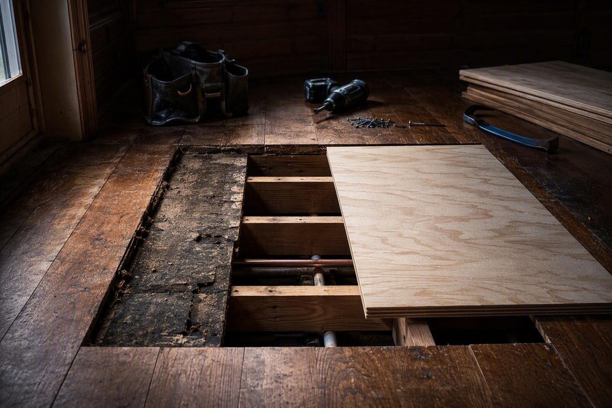
To replace a localized section of subfloor, first stop the moisture source, expose enough of the floor to find firm material, and confirm that each replacement edge will have support permitted by the panel and framing system. A wet panel that remains strong may sometimes be dried instead of removed; spongy, rotted, delaminated, or structurally unsound material generally must come out. If the opening reveals damaged framing, uncertain utilities, widespread decay, or damage beneath walls and fixed fixtures, stop treating the job as a simple panel patch.
First decide: dry it, patch it, or open a larger area
Do not begin by drawing a rectangle around a stain. First decide whether the panel can remain, whether the damage suits a contained patch, or whether the floor needs broader investigation.
| Condition | Retain and dry | Localized patch | Open larger or escalate |
|---|---|---|---|
| Moisture source resolved | Possible if the panel remains sound | Required before patching | Stop if the source is unknown or active |
| Panel firm or spongy | Firm, strong material may be retainable | Remove isolated soft or unsound material | Widespread softness needs broader evaluation |
| Known saturation history | More plausible after brief, controlled wetting | Consider removal after prolonged deterioration | Repeated or unknown wetting warrants wider inspection |
| Visible damage extent | Staining without lost strength may remain | Damage can be cut back to firm material | Damage continues beneath walls or fixtures |
| Adjacent panel condition | Surrounding material is firm | Cut lines can reach sound panel | Softness or swelling continues outward |
| Framing condition | Joists and bearing remain sound | The patch can receive suitable edge support | Framing is soft, cracked, decayed, altered, or uncertain |
Wet does not automatically mean ruined. After the leak has been corrected, a panel that remains strong and solid may sometimes be exposed, ventilated, and allowed to dry. Spongy, rotted, or otherwise unsound material generally needs removal, as explained in LP’s guidance on evaluating water-damaged subflooring.
Softness, localized sagging, recurring grout cracks, lifting flooring seams, musty odors, ceiling stains below, and a rocking toilet are reasons to investigate. None proves by itself that the subfloor is rotten.
A contained patch is appropriate only when:
- The moisture source has been identified and corrected.
- Damaged material can be cut back to firm panel.
- The surrounding panel is suitable to retain.
- Each replacement edge will have support permitted by the specific assembly.
- The opening does not require improvisation around damaged or unidentified framing.
- The repaired assembly can support the intended finish floor.
Move away from the localized-patch workflow when damage is widespread, continues beneath a wall, tub, shower, cabinet, or other fixed load, or reaches compromised framing. A room-scale replacement involves different sequencing and support decisions.
Complete the pre-cut worksheet
Record the following before buying a replacement panel or setting a saw depth. “Unknown” is a useful answer because it identifies what must be resolved before cutting.
| Item | Record before cutting |
|---|---|
| Leak or moisture source | ______ |
| How and when it was corrected | ______ |
| Measured existing panel thickness | ______ |
| Visible panel stamp or Performance Category | ______ |
| Panel material: plywood or OSB | ______ |
| Joist spacing, center to center | ______ |
| Framing: solid-sawn or engineered | ______ |
| Edge profile: square or tongue-and-groove | ______ |
| Planned finish flooring | ______ |
| Support planned beneath each patch edge | ______ |
| Plumbing supply lines | Location/status: ______ |
| Drain and vent lines | Location/status: ______ |
| Electrical wiring | Location/status: ______ |
| Gas lines | Location/status: ______ |
| Ducts or mechanical services | Location/status: ______ |
| Other concealed services | Location/status: ______ |
| Toilet flange or penetration | Removal/attachment plan: ____ |
| Wall, tub, cabinet, or fixed load nearby | ______ |
| Underlayment or tile substrate | ______ |
| Expected completed floor height | ______ |
Existing nail or screw lines can suggest where joists run, but they do not prove the framing layout. Confirm the layout from an accessible edge, from below, or through a controlled inspection area.
Physically measure the existing panel before setting cutting depth. Do not rely only on nominal descriptions or a damaged or incomplete stamp.
Do not cut while concealed services remain uncertain. A documented bathroom project begins by locating framing and establishing panel thickness, but its cutting and support methods apply to that particular repair rather than every floor (see the project sequence).
Bathroom openings require several additional decisions:
- Can the toilet flange be removed or otherwise handled without damaging the drain?
- Where do supply, drain, and vent lines run?
- Does the panel continue beneath a tub, shower, partition, vanity, or cabinet?
- How will the flange or other fixture attachment be supported?
- What structural panel, underlayment, substrate, and finish flooring will be installed?
- What will the completed floor height be?
- How will penetrations and fixture seals work with any required waterproofing?
Do not assume that one flange-hole diameter, flange elevation, or two-piece patch arrangement fits every bathroom. Those details depend on the plumbing component, floor assembly, applicable requirements, and available access.
Before-cutting checkpoint: Do not proceed until the leak has been corrected, the framing type and panel thickness are known, concealed services have been located, and the proposed opening has a credible support plan.
Expose the damage and plan supported cut lines
Finish flooring, underlayment, tile substrate, baseboards, and fixtures may need to be removed or pulled back before the structural panel can be evaluated. A small stain may conceal a larger weakened area, while a dramatic stain may remain on material that is still firm.
Map the opening back to sound material instead of tracing only visible discoloration or the softest spot. Plan the cuts around both panel condition and the support available to the replacement.
A. EDGE OVER A SOUND JOIST
      retained panel | replacement
  ------------------|------------------
       shared bearing on sound joist
                [ JOIST ]

B. EDGE BETWEEN JOISTS
      retained panel | replacement
  ------------------|------------------
        assembly-appropriate support
     [JOIST]                    [JOIST]

C. EDGE BESIDE A WALL OR FIXED LOAD
        WALL / TUB / CABINET
  ================================
      uncertain panel edge or load
  -------- planned opening --------
        STOP: verify load and support

D. EDGE AROUND A PENETRATION
             ( penetration )
  -----------(     )---------------
       plan panel support without
       crowding pipes or altering framing
Where the layout permits, retained and replacement panel edges may share a sound joist, provided both sides receive reliable bearing. Locating a joist somewhere beneath the cut is not enough if the cut leaves inadequate support.
An edge between joists needs support permitted by the actual panel and framing assembly. That may be an appropriate added support detail or, in a qualifying floor-panel system, an intact compatible edge joint. Cut-off tongues, mismatched profiles, and small perimeter patches should not be assumed to retain tongue-and-groove support.
Hands-on tutorials often show solid-lumber blocking or plywood backing for particular openings. One sponsored bathroom tutorial, for example, lays out a patch around joists and adds support beneath an otherwise unsupported edge (see the demonstrated layout). Its lumber size, screw length, adhesive choice, and dimensions are project examples—not universal specifications.
Do not improvise a support detail where:
- A wall, tub, shower, cabinet, or other load complicates access.
- The panel disappears beneath a possible bearing component.
- A joist top or side is damaged.
- The floor uses engineered I-joists or another proprietary system.
- Plumbing prevents the proposed support from bearing properly.
- The support would require altering framing.
- It is unclear how the support will transfer load.
Remove the damaged panel in a controlled sequence
Once the cut layout, framing, utilities, and edge-support plan are established:
- Trace or mark the opening so the cuts reach firm material and planned support.
- Set the cutting tool for the measured panel, recognizing that depth control is not a substitute for locating concealed services.
- Make only the accessible, planned cuts; corners and areas near penetrations may require a different tool and greater control.
- Separate the damaged section without using fragile retained edges as though they were structural supports.
- Pause if the panel does not release as expected or if removal exposes unanticipated framing, services, moisture, or deterioration.
- Reassess the opening after the damaged material is out. Do not force the replacement to follow the original outline if the exposed condition shows that the repair must expand.
This is intentionally a bounded removal sequence rather than a universal cutting specification. Tool choice and access vary, particularly around plumbing, walls, adhesive, and engineered framing.
Inspect the framing before closing the opening
Clean the opening enough to inspect the exposed assembly. Check:
- Joist tops, sides, and visible ends.
- Adjacent panel edges and underside surfaces.
- Plumbing joints, supply lines, drains, and fixture connections.
- Old adhesive or fasteners that could prevent level bearing.
- The cavity for continuing moisture or deterioration.
- The actual support available beneath each replacement edge.
Look for softness, substantial decay, cracking, significant alteration, and loss of reliable bearing. The condition that damaged the subfloor may also have affected the joists. If damaged framing may require replacement, consult a design professional rather than concealing it beneath a larger patch.
Engineered-joist warning: Do not transfer ordinary solid-lumber cutting, drilling, blocking, or repair details to an I-joist. Identify the manufacturer and series where possible, then obtain manufacturer-specific instructions or qualified structural guidance before altering or repairing it. A bathroom repair discussion in which the advice changed after I-joists were identified illustrates why framing identification must come first (review the project discussion).
Significant or uncertain mold conditions should also pause the project for appropriate assessment. Opening a cavity may reveal a different condition from the small area visible at the surface.
After-opening checkpoint: Do not install the patch until the moisture source is corrected, the framing and retained panel are suitable to remain, exposed systems have been checked, and each replacement edge has support permitted by the assembly.
Choose a replacement panel that matches the floor system
Both plywood and OSB can be suitable subfloor materials. The correct choice depends on panel rating, span rating, thickness or Performance Category, support spacing, applied load, edge profile, structural design, and finish-floor assembly.
Use the existing stamp as a starting point, but verify the panel physically.
| Label item | What it tells you |
|---|---|
| Plywood or OSB | How the structural wood panel is manufactured; either may be floor-rated |
| Thickness or Performance Category | Stamped panel category to compare with physical measurement and floor design |
| Span rating | Maximum recommended support spacing for the rated application |
| APA Rated Sheathing | Structural panel that may serve as subfloor beneath another layer |
| APA Rated Sturd-I-Floor | Panel for certain combined subfloor-underlayment systems |
| Structural I | Enhanced shear and cross-panel performance where required |
| T&G | Tongue-and-groove edge for a compatible joint system |
For APA Rated Sheathing with a two-number span rating, the second number gives the maximum recommended support spacing for subfloor use. That number does not by itself establish that the panel suits the complete floor assembly (APA’s floor-system guidance).
Rated Sheathing commonly serves as structural subfloor beneath separate underlayment or another structural finish layer. Sturd-I-Floor can combine subfloor and underlayment functions in certain assemblies. Panels labeled only Wall-16 or Wall-24 are not intended for floors, while Structural I panels are manufactured for applications requiring enhanced shear and cross-panel performance. The label does not establish whether a particular house requires Structural I (APA’s OSB grade explanation).
Tongue-and-groove edges can eliminate long-edge blocking only where the specified panel system and installation are designed to use the joint that way. A small patch with cut, damaged, or mismatched edges may require separate support.
The finish floor also affects panel selection. Carpet with pad, hardwood, resilient flooring, fully adhered carpet, and ceramic tile can require different combinations of structural panel, underlayment, substrate, flatness, stiffness, and surface preparation.
Do not select one universal thickness for every repair. Coordinate:
- Measured existing panel thickness and stamped Performance Category.
- Support spacing and panel span rating.
- Framing type and structural design.
- Edge profile and planned support.
- Applied loads.
- Finish-floor and underlayment requirements.
- Completed floor elevation.
- Panel instructions and applicable building requirements.
Matching the opening’s thickness is important, but thickness alone does not establish suitability.
Dry-fit, space, glue, and fasten the patch
Cut the replacement only after the opening has been accurately mapped. Dry-fit it before applying adhesive. Confirm that it sits level with the retained floor, clears penetrations appropriately, and engages the planned support.
APA generally recommends approximately 1/8 inch of space at structural-panel edge and end joints, including tongue-and-groove joints, to accommodate moisture-related dimensional change. Plywood and OSB change dimensions as moisture content changes, and tightly butted panels can buckle as they expand. This is a general recommendation, not a universal code rule; the selected panel manufacturer’s instructions control when they differ (APA’s panel-spacing guidance).
For a glued floor system:
- Remove water, dust, debris, and adhesive ridges from bearing surfaces.
- Confirm that framing and added supports are level and suitable.
- Use an adhesive compatible with the selected panel and framing.
- Apply only as quickly as the patch can be positioned.
- Seat the panel while maintaining the specified joint clearance.
- Fully fasten it before the adhesive skins over or sets.
Adhesive does not replace mechanical fasteners. In a compatible glued floor system, adhesive and fasteners work together to increase stiffness and help reduce squeaks and nail popping.
The fastening schedule must come from the selected panel, framing, adhesive system where relevant, finish-floor requirements, and applicable rules. Do not copy a tutorial’s panel thickness, bead size, fastener length, fastener type, edge distance, or spacing without confirming that it applies to the actual assembly.
Before rebuilding the upper layers, check for:
- Support permitted by the assembly at each edge.
- No rocking or raised corners.
- The specified joint clearance.
- Flush transitions to retained panels.
- Properly seated fasteners without damaged panel surfaces.
- Correctly located and supported plumbing penetrations.
- No debris, adhesive, or fastener heads interfering with the next layer.
Rebuild the layers above the structural panel
Replacing the wood panel restores only one part of the floor. The layers above it must suit the finish flooring and the room’s moisture exposure.
TOP
┌──────────────────────────────────────┐
│ Finish flooring                     │
├──────────────────────────────────────┤
│ Membrane or waterproofing, if needed│
├──────────────────────────────────────┤
│ Underlayment or tile substrate      │
├──────────────────────────────────────┤
│ Structural subfloor panel           │
├──────────────────────────────────────┤
│ Joists and permitted edge supports  │
└──────────────────────────────────────┘
BOTTOM

At fixtures and penetrations:
completed floor height
+ waterproofing transitions
+ flange or fixture attachment
+ final fixture seals
Structural subfloor and underlayment are not interchangeable. The subfloor spans between supports and transfers loads to the framing. Underlayment or a tile substrate serves the finish-floor system. A membrane or waterproofing layer has another function, while fixture seals must prevent water from re-entering the assembly.
Different finishes call for different rebuilds:
- Carpet with pad may suit an appropriate single-layer floor-panel system.
- Hardwood has substrate, flatness, fastening, and moisture requirements.
- Resilient flooring requires careful surface preparation because seams and fasteners can telegraph through.
- Fully adhered carpet may require underlayment compatible with its adhesive.
- Ceramic tile requires a complete tile-suitable substrate system, not merely a patch that feels firm.
Follow the finish-floor and underlayment manufacturers’ requirements for flatness, preparation, compatibility, fastening, joint treatment, and installation. Do not assume that structural wood panels are automatically direct-bond tile surfaces or finished substrates for resilient flooring.
In bathrooms, coordinate plumbing penetrations, flange attachment, required waterproofing, and completed floor height before reinstalling fixtures. No single tile substrate, membrane, flange-hole size, flange elevation, or waterproofing detail fits every system.
Before-covering checkpoint:
- The original leak has been corrected.
- Retained materials and the cavity are suitable to close.
- Plumbing connections show no continuing leakage.
- Penetrations align with the rebuilt layers.
- Fixture attachments have sound support.
- New fixture seals will not reintroduce moisture.
- The completed assembly meets the applicable panel and finish-floor instructions.
Know when this is no longer a DIY panel patch
Stop work and bring in the appropriate trade or specialist when any of the following applies:
- [ ] The leak or moisture source remains unresolved.
- [ ] Concealed plumbing, wiring, gas lines, ducts, or other services cannot be located confidently.
- [ ] Rot or softness is widespread or continues beyond the opening.
- [ ] A joist is soft, substantially decayed, cracked, altered, or missing reliable bearing.
- [ ] An engineered joist is damaged or the repair would alter it.
- [ ] A patch edge has no support detail permitted by the actual assembly.
- [ ] Damage runs beneath a wall, tub, shower, cabinet, partition, or significant fixed load.
- [ ] Mold conditions are significant, concealed, or uncertain.
- [ ] The panel rating, thickness, or framing layout cannot be identified.
- [ ] The finish-floor assembly cannot be reconciled with the repaired structure or completed height.
Call a plumber when a supply line, drain, toilet flange, shower, or tub leak cannot be confidently corrected before the floor is closed. Seek structural or design guidance when framing may require replacement or when walls, tubs, cabinets, or other loads complicate removal and support.
A room-scale subfloor replacement is not simply a larger patch. The localized cut-and-support workflow does not resolve those conditions.
Finish with three decisions:
- Diagnose before cutting. Correct the moisture source, identify the panel and framing, locate concealed services, and decide what material can remain.
- Inspect before patching. Confirm sound framing, firm adjacent panels, a suitable cavity, and support permitted by the assembly at every replacement edge.
- Verify the full floor assembly before covering. Coordinate the panel, spacing, adhesive, fasteners, underlayment, waterproofing, finish flooring, and fixture details for the actual system.